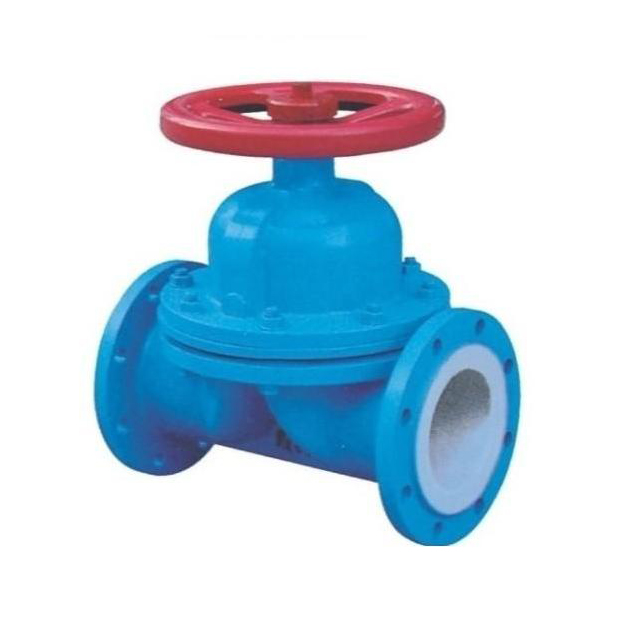

A shut-off valve refers to a valve whose closing element (disc) is driven by the valve stem and moves up and down along the central axis of the valve seat. It is mainly used in pipelines to connect or cut off the medium in the pipeline, but cannot be used for throttling.
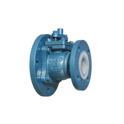
1. The basic series of globe valves are J41F46 straight through, J45F46 direct current, and J44 F46 angle globe valves. They have the advantages of compact structure, flexible opening and closing, strong corrosion resistance, and short stroke (usually 1/4 of the nominal diameter). They are widely used as cutoff media in pipeline systems such as petroleum and chemical industries. However, it should be emphasized that flow regulation is strictly prohibited for fluorine lined globe valves to prevent high-speed medium flow generated at the throttling port from damaging the sealing surface. The valve disc and valve stem are designed as an integrated structure to prevent the possibility of internal components flushing out of the valve body due to pipeline pressure fluctuations. The structure is compact and safe to use.
2. Valve manufacturing follows specifications:
a. Design and manufacturing in accordance with GB 12233/GB 12235 standards;
b. The structural length shall comply with GB 12221 (long short series);
c. The flange size shall be in accordance with JB 78/JB 79 (GB.HG. SH) standard;
d. The pressure test shall be carried out in accordance with the GB/T 13927 standard;
e. The logo shall comply with the GB 12220 standard;
f. Supply according to JB/T 7928 standard.
3. Driving method
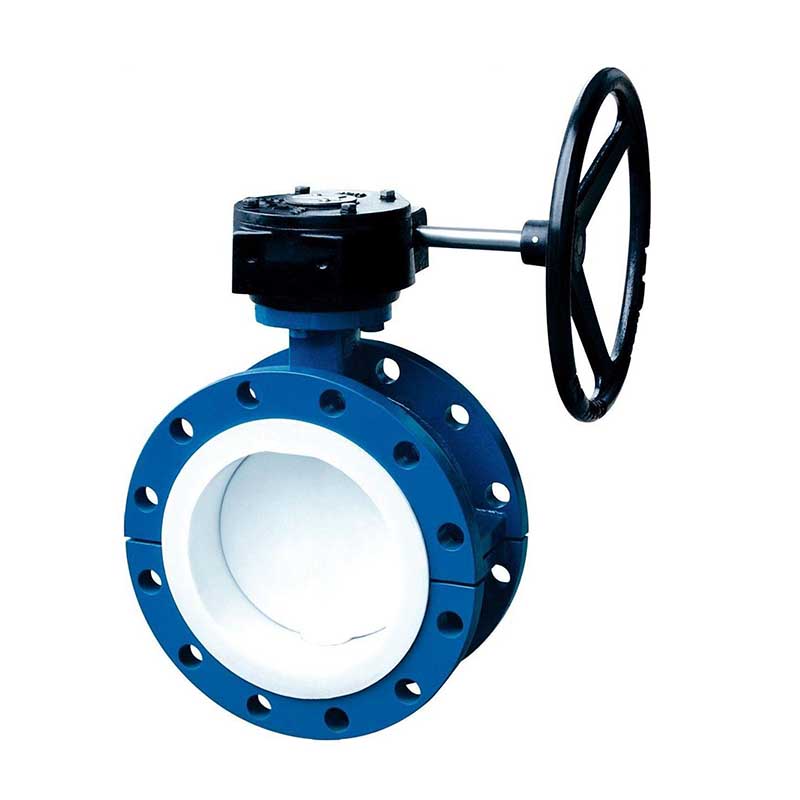
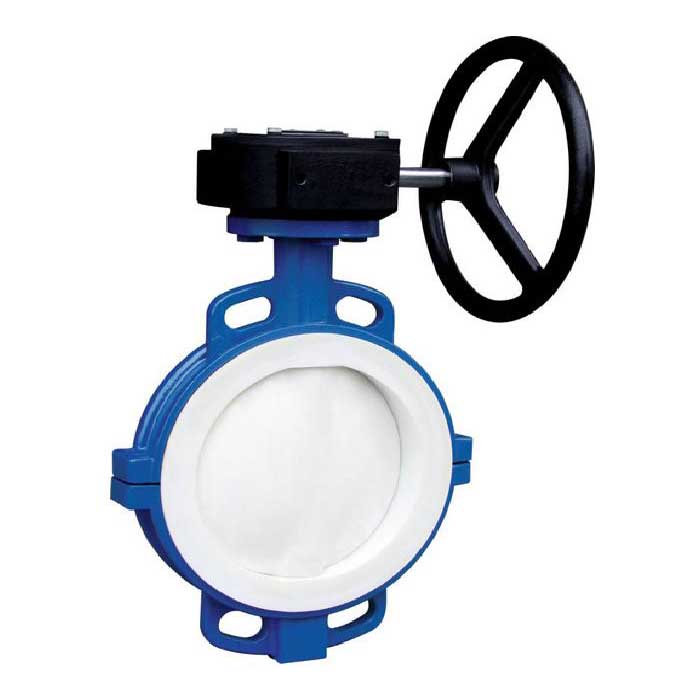
This product can be manufactured with handwheel, pneumatic, electric and other driving methods according to user needs.
4. Valve Connection Standards
This product can be manufactured according to user needs and supplied in accordance with standards such as ANSI (American Standard), DIN (German Standard), JIS (Japanese Standard), etc.
Compliance with regulations | |
design and manufacturing | GB 12239 |
Structure length | GB 12221/JB 1688 |
Flange size | JB78/JB79(GB,HG,SH) |
Pressure test | GB/T 13927 |
sign | GB 12220 |
supply of material | GB/T12252 |
Flange connected globe valve
·The design and manufacturing comply with Chinese national standards.
·Basic structural form: through type, DC type
·Nominal pressure: PN1.0~2.5 (MPa)
·Nominal diameter DN15-350 (mm)
·Basic model (fully lined)
| hand movement | J41F46 | gear drive | F441F46 |
J45F46 | J541F46 | ||
Pneumatic | J6B41F46 | Electric | J941F46 |
List of Main Component Materials
| Serial Number | Part Name | Gray cast iron | cast steel | stainless steel | Ultra low carbon stainless steel | ||
Z | C | P | R | PL | RL | ||
1 | Valve body and valve cover | HT250 | WCB | CF8 | CF8M | CF3 | CF3M |
2 | Valve disc and stem | 35 | 1Cr13 | 1Cr18Ni9 | 1Cr18Ni12M02Ti | 00Cr18Ni10 | 00CR17NI14M02 |
3 | eyelet bolt | 35 | 35 | 1Cr17Ni2 | 1Cr17Ni2 | 1Cr17Ni2 | 1Cr17Ni2 |
4 | Lining layer/valve seat | FEP(F46) PCTFE(F3) PFA(Deeply soluble polytetrafluoroethylene) | |||||
5 | filler | PTFE(F4) PTFE(F4) | |||||
6 | Packing gland | WCB | WCB | CF8 | CF8M | CF3 | CF3M |
7 | stem nut | ZCuA/10Fe3 | ZCuA/10Fe3 | ||||
8 | bolt | 35 | 35 | 1Cr17Ni2 | 1Cr17Ni2 | 1Cr17Ni9Ti | 1Cr17Ni9Ti |
9 | nut | 45 | 45 | 0Cr18Ni9 | 0Cr18Ni9 | 0Cr18Ni9 | 0Cr18Ni9 |
10 | handwheel | HT200 | HT200 | WCC | WCC | WCC | WCC |
Main connection dimensions and weight J41F46
Nominal Diameter | Standard value | Reference value | |||||||||||
DN (mm) | NPS (inch) | L | D | D1 | D2 | f | b | Z-Φd | D0 | H1 | H2 | W(Kg) | |
PN1.0(MPa) | |||||||||||||
15 | 1/2 | 130 | 95 | 65 | 45 | 2 | 14 | 4-Φ14 | 100 | 235 | 260 | 6.5 | |
20 | 3/4 | 150 | 105 | 75 | 55 | 2 | 16 | 4-Φ14 | 100 | 240 | 265 | 7 | |
25 | 1 | 160 | 115 | 85 | 65 | 2 | 16 | 4-Φ14 | 120 | 245 | 270 | 7.8 | |
32 | 11/4 | 180 | 135 | 100 | 78 | 2 | 18 | 4-Φ18 | 140 | 255 | 285 | 11 | |
40 | 11/2 | 200 | 145 | 110 | 85 | 3 | 18 | 4-Φ18 | 140 | 285 | 315 | 13 | |
50 | 2 | 230 | 160 | 125 | 100 | 3 | 20 | 4-Φ18 | 160 | 295 | 330 | 15 | |
65 | 21/2 | 290 | 180 | 145 | 120 | 3 | 20 | 4-Φ18 | 180 | 350 | 395 | 23 | |
80 | 3 | 310 | 195 | 160 | 135 | 3 | 22 | 4-Φ18 | 240 | 395 | 445 | 38 | |
100 | 4 | 350 | 215 | 180 | 155 | 3 | 22 | 8-Φ18 | 240 | 450 | 490 | 42 | |
125 | 5 | 400 | 245 | 210 | 185 | 3 | 24 | 8-Φ18 | 280 | 525 | 555 | 55 | |
150 | 6 | 480 | 280 | 240 | 210 | 3 | 24 | 8-Φ23 | 320 | 605 | 645 | 77 | |
200 | 8 | 495 | 335 | 295 | 265 | 3 | 26 | 8-Φ23 | 360 | 645 | 765 | 135 | |
250 | 10 | 622 | 390 | 350 | 320 | 3 | 28 | 12-Φ23 | 400 | 685 | 805 | 220 | |
300 | 12 | 698 | 440 | 400 | 368 | 4 | 28 | 12-Φ23 | 400 | 710 | 814 | 277 | |
350 | 14 | 787 | 500 | 460 | 428 | 4 | 30 | 16-Φ23 | 450 | 750 | 855 | 320 | |
PN 1.6(MPa) | |||||||||||||
15 | 1/2 | 130 | 95 | 65 | 45 | 2 | 14 | 4-Φ14 | 100 | 240 | 265 | 7 | |
20 | 3/4 | 150 | 105 | 75 | 55 | 2 | 16 | 4-Φ14 | 10 | 245 | 270 | 7.6 | |
25 | 1 | 160 | 115 | 85 | 65 | 2 | 16 | 4-Φ14 | 120 | 250 | 275 | 8.2 | |
32 | 11/4 | 180 | 135 | 100 | 78 | 2 | 18 | 4-Φ18 | 140 | 260 | 290 | 12 | |
40 | 11/2 | 200 | 145 | 110 | 85 | 3 | 18 | 4-Φ18 | 140 | 285 | 320 | 14 | |
50 | 2 | 230 | 160 | 125 | 100 |
| 20 | 4-Φ18 | 160 | 300 | 335 | 18 | |
65 | 21/2 | 290 | 180 | 145 | 120 | 3 | 20 | 4-Φ18 | 180 | 355 | 400 | 26 | |
80 | 3 | 310 | 195 | 160 | 135 | 3 | 22 | 8-Φ18 | 240 | 400 | 450 | 40 | |
100 | 4 | 350 | 215 | 180 | 155 | 3 | 24 | 8-Φ18 | 240 | 455 | 495 | 50 | |
125 | 5 | 400 | 245 | 210 | 185 | 3 | 26 | 8-Φ18 | 280 | 530 | 560 | 65 | |
150 | 6 | 480 | 280 | 240 | 210 | 3 | 28 | 8-Φ23 | 320 | 610 | 650 | 85 | |
200 | 8 | 495 | 335 | 295 | 265 | 3 | 30 | 12-Φ23 | 360 | 650 | 770 | 150 | |
250 | 10 | 622 | 405 | 355 | 320 | 3 | 32 | 12-Φ25 | 400 | 690 | 810 | 245 | |
300 | 12 | 698 | 460 | 410 | 375 | 4 | 34 | 12-Φ25 | 400 | 730 | 845 | 295 | |
PN 2.5(MPa) | |||||||||||||
15 | 1/2 | 130 | 95 | 65 | 45 | 2 | 16 | 4-Φ14 | 120 | 240 | 265 | 7.5 | |
20 | 3/4 | 150 | 105 | 75 | 55 | 2 | 16 | 4-Φ14 | 120 | 245 | 270 | 8 | |
25 | 1 | 160 | 115 | 85 | 65 | 2 | 16 | 4-Φ14 | 140 | 250 | 275 | 9 | |
32 | 11/4 | 180 | 135 | 100 | 78 | 2 | 18 | 4-Φ18 | 160 | 260 | 290 | 13 | |
40 | 11/2 | 200 | 145 | 110 | 85 | 3 | 18 | 4-Φ18 | 180 | 285 | 320 | 15 | |
50 | 2 | 230 | 160 | 125 | 100 | 3 | 20 | 4-Φ18 | 180 | 300 | 335 | 20 | |
65 | 21/2 | 290 | 180 | 145 | 120 | 3 | 22 | 8-Φ18 | 240 | 355 | 400 | 28 | |
80 | 3 | 310 | 195 | 160 | 135 | 3 | 22 | 8-Φ18 | 280 | 400 | 450 | 42 | |
100 | 4 | 350 | 230 | 190 | 160 | 3 | 24 | 8-Φ23 | 320 | 455 | 495 | 57 | |
125 | 5 | 400 | 270 | 220 | 188 | 3 | 28 | 8-Φ25 | 320 | 530 | 560 | 71 | |
150 | 6 | 480 | 300 | 250 | 218 | 3 | 30 | 8-Φ25 | 360 | 610 | 650 | 90 | |
Main connection dimensions and weight J44F46
Nominal Diameter | Standard value | Reference value | |||||||||||
DN (mm) | NPS(inch) | L | D | D1 | D2 | f | b | Z-Φd | D0 | H1 | H2 | W(Kg) | |
PN1.0(MPa) | |||||||||||||
15 | 1/2 | 65/90 | 95 | 65 | 45 | 2 | 14 | 4-Φ14 | 100 | 235 | 265 | 7 | |
20 | 3/4 | 75/95 | 105 | 75 | 55 | 2 | 16 | 4-Φ14 | 100 | 240 | 270 | 7.5 | |
25 | 1 | 80/00 | 115 | 85 | 65 | 2 | 16 | 4-Φ14 | 120 | 245 | 275 | 8 | |
32 | 11/4 | 95/105 | 135 | 100 | 78 | 2 | 18 | 4-Φ18 | 120 | 255 | 290 | 12 | |
40 | 11/2 | 100/115 | 145 | 110 | 85 | 3 | 18 | 4-Φ18 | 140 | 285 | 325 | 14 | |
50 | 2 | 115/125 | 160 | 125 | 100 | 3 | 20 | 4-Φ18 | 140 | 295 | 335 | 19 | |
65 | 21/2 | 145 | 180 | 145 | 120 | 3 | 20 | 4-Φ18 | 160 | 350 | 400 | 27 | |
80 | 3 | 155 | 195 | 160 | 135 | 3 | 22 | 4-Φ18 | 160 | 395 | 450 | 42 | |
100 | 4 | 175 | 215 | 180 | 155 | 3 | 22 | 8-Φ18 | 180 | 450 | 495 | 50 | |
125 | 5 | 200 | 245 | 210 | 185 | 3 | 24 | 8-Φ18 | 180 | 525 | 560 | 64 | |
150 | 6 | 240/225 | 280 | 240 | 210 | 3 | 24 | 8-Φ23 | 240 | 605 | 650 | 85 | |
200 | 8 | 275 | 335 | 295 | 265 | 3 | 26 | 8-Φ23 | 240 | 645 | 770 | 105 | |
250 | 10 | 325 | 390 | 350 | 320 | 3 | 28 | 12-Φ23 | 280 | 685 | 800 | 135 | |
300 | 12 | 375 | 440 | 400 | 368 | 4 | 28 | 12-Φ23 | 280 | 710 | 835 | 155 | |
PN 1.6(MPa) | |||||||||||||
15 | 1/2 | 65/90 | 95 | 65 | 45 | 2 | 14 | 4-Φ14 | 100 | 240 | 265 | 7 | |
20 | 3/4 | 75/95 | 105 | 75 | 55 | 2 | 16 | 4-Φ14 | 100 | 245 | 270 | 7.5 | |
25 | 1 | 80/100 | 115 | 85 | 65 | 2 | 16 | 4-Φ14 | 120 | 250 | 275 | 8.5 | |
32 | 11/4 | 95/105 | 135 | 100 | 78 | 2 | 18 | 4-Φ18 | 140 | 260 | 290 | 12 | |
40 | 11/2 | 100/115 | 145 | 110 | 85 | 3 | 18 | 4-Φ18 | 140 | 285 | 325 | 14 | |
50 | 2 | 115/125 | 160 | 125 | 100 | 3 | 20 | 4-Φ18 | 160 | 300 | 335 | 19 | |
65 | 21/2 | 145 | 180 | 145 | 120 | 3 | 20 | 4-Φ18 | 180 | 355 | 400 | 27 | |
80 | 3 | 155 | 195 | 160 | 135 | 3 | 22 | 8-Φ18 | 240 | 400 | 450 | 42 | |
100 | 4 | 175 | 215 | 180 | 155 | 3 | 24 | 8-Φ18 | 240 | 455 | 495 | 50 | |
125 | 5 | 200 | 245 | 210 | 185 | 3 | 26 | 8-Φ18 | 280 | 530 | 560 | 64 | |
150 | 6 | 240/225 | 280 | 240 | 210 | 3 | 28 | 8-Φ23 | 320 | 610 | 650 | 85 | |
200 | 8 | 275 | 335 | 295 | 265 | 3 | 30 | 8-Φ23 | 360 | 650 | 770 | 155 | |
PN 2.5(MPa) | |||||||||||||
15 | 1/2 | 65/90 | 95 | 65 | 45 | 2 | 16 | 4-Φ14 | 120 | 245 | 270 | 7.5 | |
20 | 3/4 | 75/95 | 105 | 75 | 55 | 2 | 16 | 4-Φ14 | 120 | 250 | 275 | 8.8 | |
25 | 1 | 80/100 | 115 | 85 | 65 | 2 | 16 | 4-Φ14 | 140 | 260 | 290 | 11 | |
32 | 11/4 | 95/105 | 135 | 100 | 78 | 2 | 18 | 4-Φ18 | 140 | 285 | 325 | 13 | |
40 | 11/2 | 100/115 | 145 | 110 | 85 | 3 | 18 | 4-Φ18 | 160 | 300 | 335 | 18 | |
50 | 2 | 115/125 | 160 | 125 | 100 | 3 | 20 | 4-Φ18 | 180 | 355 | 400 | 31 | |
*The L value in the table conforms to the GB12221 long series, where the numerator represents the L value according to JB96.
Related Information
COPYRIGHT © 2023 Zhejiang Zhuopu Anti corrosion Technology Co., Ltd Copyright sitemap
 Contact
 Message
 Home
Home