
Ball valves use a ball core with a circular through-hole as the opening and closing element. The ball core rotates around the centerline of the valve body with the valve stem to achieve the purpose of opening and closing the valve.
The basic series of ball valves is Q41F46 type, which can be divided into two types of structures: two-piece and three piece. In addition to the small fluid resistance, fast opening and closing speed, and simple structure that ordinary ball valves have; It also has the following advantages
(1) Ball valves with FEP lining layer have extremely high chemical stability and can be used in any highly corrosive medium except for molten alkali metals and elemental fluorine;
(2) Adopting a full bore, floating ball structure, the valve can be closed without leakage within the entire pressure range, making it more convenient for ball cleaning and pipeline maintenance of the pipeline system;
(3) The ball of the opening and closing part is integrated with the valve stem casting (forging), which eliminates the possibility of valve stem impacting the pressure bearing part due to pressure changes, fundamentally ensuring the safety of use in engineering;
(4) The structure is compact and reasonable, with the smallest internal cavity space of the valve body, reducing medium retention. In addition, the special molding process ensures good density of the sealing surface, and the combination of herringbone ring PTFE packing ensures zero leakage of the valve;
(5) The two piece and three piece structures can adapt to various pipeline systems and working conditions with different requirements. Among them, the three piece ball valve allows the main valve body to be separated from the two sides, and can achieve online rapid replacement and maintenance.
1、 Valve manufacturing follows specifications:
a. Design and manufacturing in accordance with GB 12237 standard;
b. The structural length shall be in accordance with GB 12221 (medium series);
c. The flange size shall be in accordance with JB 78/JB 79 (GB.HG. SH) standard;
d. The pressure test shall be carried out in accordance with the GB/T 13927 standard; e. The logo shall comply with the GB 12220 standard;
f. Supply according to JB/T7928 standard.
2、 Driving method
This product can be manufactured according to user needs, including handle, worm gear, pneumatic, electric and other driving methods.
3、 Valve Connection Standards
This product can be manufactured according to user needs and supplied in accordance with standards such as ANSI (American Standard), DIN (German Standard), JIS (Japanese Standard), etc.
Compliance with regulations | |
design and manufacturing | GB 12237 |
Structure length | GB12221(medium series) |
Flange size | JB78/JB79(GB,HG,SH) |
Pressure test | GB/T 13927 |
sign | GB12220 |
supply of material | GB/T12252 |
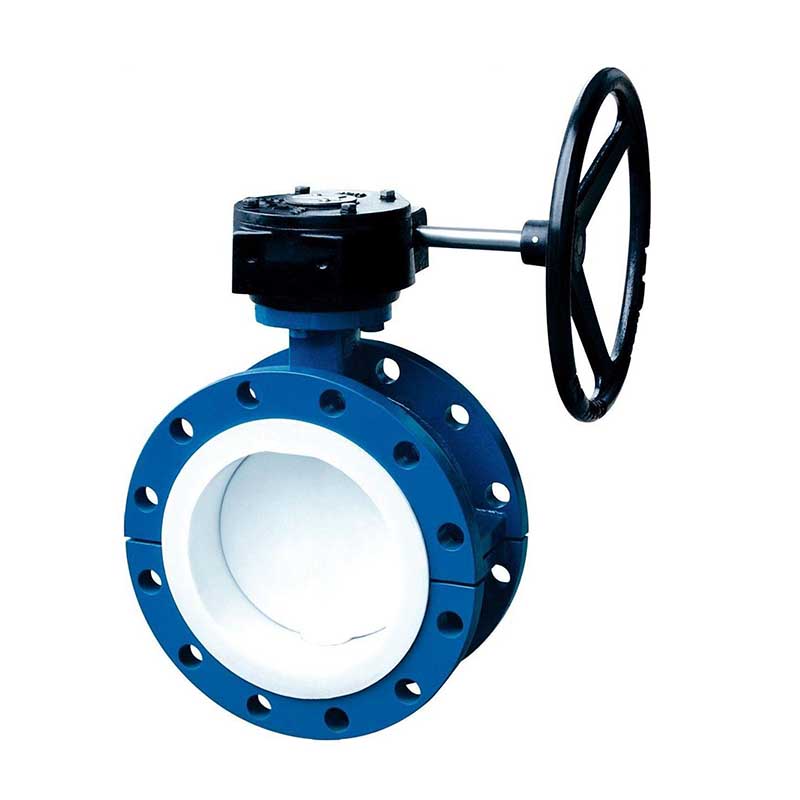
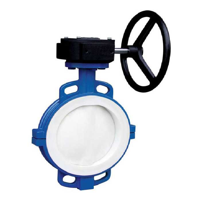
Flange connected ball valve (two piece, three piece)
·The design and manufacturing comply with Chinese national standards.
·Nominal pressure DN1.0~2.5 (MPa)
·Nominal diameter DN15-250 (mm)
·Basic model
| hand movement | Q41F4(fully lined) | pneumatic | Q641F4(fully lined) |
Q41F46(fully lined) | Q641F46(fully lined) | ||
Worm gear transmission | Q341F4(fully lined) | Electric | Q941F4(fully lined) |
Q341F46(fully lined) | Q941F46(fully lined) |
List of Main Component Materials
| Serial Number | Part Name | Gray cast iron | cast steel | stainless steel | Ultra low carbon stainless steel | |||
Z | C | P | R | PL | RL | |||
1 | Valve body and end cover | HT250 | WCB | CF8 | CF8M | CF3 | CF3M | |
2 | ball | WCB | WCB | CF8 | CF8M | CF3 | CF3M | |
3 | Lining layer/valve acne | FEP(F46) PCTFE(F3) PFA(PFA) | ||||||
4 | Packing gland | HT250 | WCB | CF8 | CF8M | CF3 | CF3M | |
5 | filler | PTFE(F4) teflon PTFE(F4)teflon | ||||||
6 | bolt | 35 | 35 | 1Cr17Ni2 | 1Cr17Ni2 | 1Cr18Ni9 | 1Cr18Ni9 | |
7 | nut | 45 | 45 | 0Cr18Ni9 | 0Cr18Ni9 | 0Cr18Ni9 | 0Cr18Ni9 | |
8 | handle | WCC | WCC | WCC | WCC | WCC | WCC | |
Nominal Diameter | Standard value | Reference value | |||||||||
DN | NPS | L | D | D1 | D2 | f | b | Z-φd | D0 | H | WT(Kg) |
PN 1.0 (MPa) | |||||||||||
15 | 1/2 | 132/130 | 95 | 65 | 45 | 2 | 14 | 4-φ14 | 120 | 80 | 2.5 |
20 | 3/4 | 140/130 | 105 | 75 | 55 | 2 | 16 | 4-φ14 | 140 | 90 | 3 |
25 | 1 | 150/140 | 115 | 85 | 65 | 2 | 16 | 4-φ14 | 160 | 100 | 4.5 |
32 | 11/4 | 165 | 135 | 100 | 78 | 2 | 18 | 4-φ18 | 160 | 110 | 5.7 |
40 | 11/2 | 180/165 | 145 | 110 | 85 | 3 | 18 | 4-φ18 | 200 | 120 | 7 |
50 | 2 | 200/203 | 160 | 125 | 100 | 3 | 20 | 4-φ18 | 250 | 135 | 9.5 |
65 | 21/2 | 220/222 | 180 | 145 | 120 | 3 | 20 | 4-φ18 | 300 | 145 | 15 |
80 | 3 | 250/241 | 195 | 160 | 135 | 3 | 22 | 4-φ18 | 350 | 185 | 19 |
100 | 4 | 280/305 | 215 | 180 | 155 | 3 | 22 | 8-φ18 | 400 | 195 | 33 |
125 | 5 | 320/356 | 245 | 210 | 185 | 3 | 24 | 8-φ18 | 500 | 210 | 58 |
150 | 6 | 360/394 | 280 | 240 | 210 | 3 | 24 | 8-φ23 | 200* | 450 | 93 |
200 | 8 | 457 | 335 | 295 | 265 | 3 | 26 | 8-φ23 | 240* | 490 | 155 |
250 | 10 | 533 | 390 | 350 | 320 | 3 | 28 | 12-φ23 | 240* | 550 | 210 |
Nominal diameter | Standard value | Reference value | |||||||||
DN | NPS | L | D | D1 | D2 | f | b | Z-φd | D0 | H | WT(Kg) |
PN 1.6 (MPa) | |||||||||||
15 | 1/2 | 132/130 | 95 | 65 | 45 | 2 | 14 | 4-φ14 | 120 | 80 | 2.5 |
20 | 3/4 | 140/130 | 105 | 75 | 55 | 2 | 16 | 4-φ14 | 140 | 90 | 3 |
25 | 1 | 150/140 | 115 | 85 | 65 | 2 | 16 | 4-φ14 | 160 | 100 | 4.5 |
32 | 11/4 | 165 | 135 | 100 | 78 | 2 | 18 | 4-φ18 | 160 | 110 | 5.7 |
40 | 11/2 | 180/165 | 145 | 110 | 85 | 3 | 18 | 4-φ18 | 200 | 120 | 7 |
50 | 2 | 200/203 | 160 | 125 | 100 | 3 | 20 | 4-φ18 | 250 | 135 | 9.5 |
65 | 21/2 | 220/222 | 180 | 145 | 120 | 3 | 20 | 4-φ18 | 300 | 145 | 15 |
80 | 3 | 250/241 | 195 | 160 | 135 | 3 | 22 | 8-φ18 | 350 | 185 | 19 |
100 | 4 | 280/305 | 215 | 180 | 155 | 3 | 22 | 8-φ18 | 400 | 195 | 33 |
125 | 5 | 320/356 | 245 | 210 | 185 | 3 | 24 | 8-φ23 | 500 | 210 | 58 |
150 | 6 | 360/394 | 280 | 240 | 210 | 3 | 36 | 8-φ23 | 200* | 450 | 93 |
200 | 8 | 457 | 335 | 295 | 265 | 3 | 28 | 12-φ23 | 240* | 490 | 155 |
Nominal diameter | Standard value | Reference value | |||||||||
DN | NPS | L | D | D1 | D2 | f | b | Z-d | D0 | H | WT(Kg) |
PN 2.5 (MPa) | |||||||||||
15 | 1/2 | 132/130 | 95 | 65 | 45 | 2 | 16 | 4-φ14 | 120 | 80 | 2.5 |
20 | 3/4 | 140/130 | 105 | 75 | 55 | 2 | 16 | 4-φ14 | 140 | 90 | 3 |
25 | 1 | 150/140 | 115 | 85 | 65 | 2 | 16 | 4-φ14 | 160 | 100 | 4.5 |
32 | 11/4 | 165 | 135 | 100 | 78 | 2 | 18 | 4-φ18 | 160 | 110 | 5.7 |
40 | 11/2 | 180/165 | 145 | 110 | 85 | 3 | 18 | 4-φ18 | 200 | 120 | 7 |
50 | 2 | 200/203 | 160 | 125 | 100 | 3 | 20 | 4-φ18 | 250 | 135 | 9.5 |
65 | 21/2 | 220/222 | 180 | 145 | 120 | 3 | 22 | 8-φ18 | 300 | 145 | 15 |
80 | 3 | 250/241 | 195 | 160 | 135 | 3 | 22 | 8-φ18 | 300 | 185 | 19 |
100 | 4 | 280/305 | 230 | 190 | 160 | 3 | 24 | 8-φ23 | 200* | 195 | 33 |
125 | 5 | 320/356 | 270 | 220 | 188 | 3 | 28 | 8-φ25 | 200* | 210 | 58 |
150 | 6 | 360/394 | 300 | 250 | 218 | 3 | 30 | 8-φ25 | 200* | 450 | 93 |
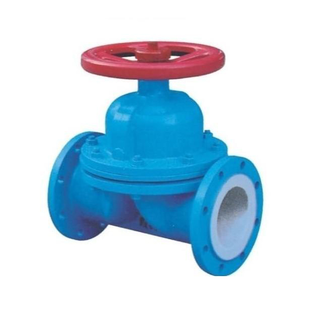
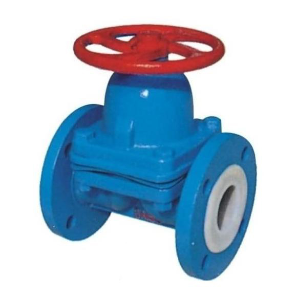
Flange connected discharge ball valve
·Nominal pressure PN1.0 (MPa)
·Nominal diameter DN40~80 (mm)
·The main materials are shown in Table B-5
Table A-7
| Nominal diameter | Standard value | Reference value | |||||||||
DN | NPS | L | D | D1 | D2 | f | b | Z-Φd | D0 | H | W(Kg) |
PN 1.0(MPa) | |||||||||||
40/65 | 11/2/21/2 | 130 | 145/180 | 110/145 | 85/120 | 3/3 | 18/20 | 4-Φ18/4-Φ18 | 200 | 110 | 8.1 |
50/80 | 2/3 | 160 | 160/195 | 125/160 | 100/135 | 3/3 | 20/22 | 4-Φ18/4-Φ18 | 250 | 125 | 9.5 |
80/125 | 3/5 | 200 | 195/245 | 160/210 | 135/185 | 3/3 | 22/24 | 4-Φ18/4-Φ18 | 400 | 100 | 19 |
*The L value is the enterprise standard, and the flange size is scanned as JB78. The left flange is one level larger than the right flange, with the numerator being the right flange size and the denominator being the left flange size.
Related Information
COPYRIGHT © 2023 Zhejiang Zhuopu Anti corrosion Technology Co., Ltd Copyright sitemap
 Contact
 Message
 Home
Home